I almost gave this post the title ‘A New Kind of DCO’, but new inventions using existing electronics don’t take place very often any more. Although I have never seen a schematic for an instrument that uses a similar method that I have used, I am sure that someone has tried it out. In fact, the CMOS chip used was pretty much created to do this exact function. I just tacked on an addition.
Lunetta Synthesizers
Before I get started, I will give a brief explanation of a Lunetta synthesizer. They are synthesizers that are created using simple logic chips. The chips are 4000 series CMOS integrated circuits. These chips operate with on or off pulses. When below the audio range, the pulses just sound like clicks. However, the pulses turn into a single sound when the frequency is in the audio range (20Hz-20,000Hz). This means that when operating in the audio range, these chips can be used as a sound source. This method of creating sounds using logic chips was made popular by an artist named Stanley Lunetta.
The Lunetta Holy Grail
As previously mentioned, Lunetta synths create sound using on and off pulses. This creates a square wave. While suitable for many situations, a square wave only contains odd harmonics and isn’t always desirable. A sawtooth wave is often preferred. However, there is no easy way to create a sawtooth wave from a square wave. There are some methods that create waves that are close to a saw, and there are very complex ways of doing it. The Lunetta Holy Grail is a simple circuit that can change a square to a saw.
The Goal
My goal was to create a method for converting a square wave to a sawtooth wave with minimal parts that was useful for Lunetta synths. Most Lunetta synths run on 5V, so the solution had to work with this power supply. This also makes it useful for use with an Arduino. I also wanted the solution to be adjustable to work on a dual rail power supply.
The Transistor Method
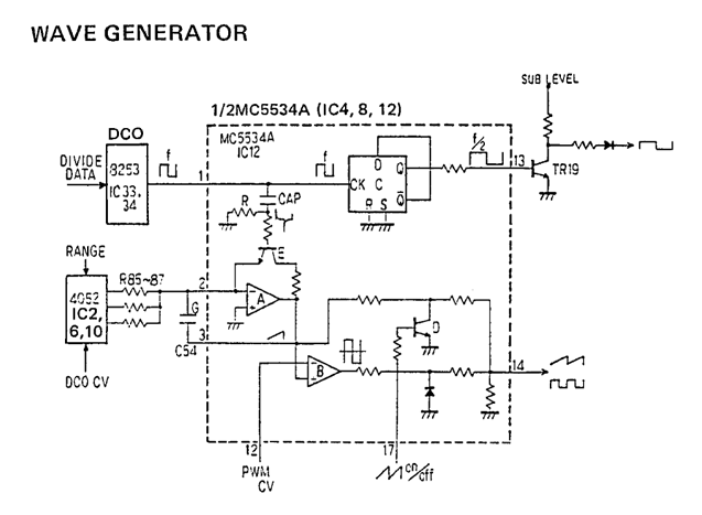
The most common method for converting a square to a saw is with a capacitor and a transistor. The incoming square wave is converted into a narrow pulse and sent to the base of a transistor. A capacitor is charged from a current source, and the transistor acts like a switch to discharge the capacitor on every pulse from the square wave.
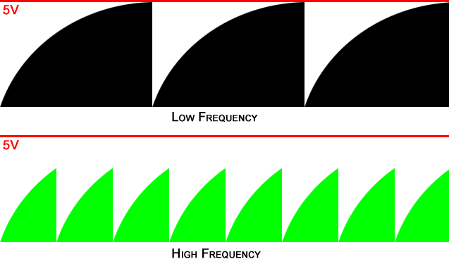
This method makes a very sloppy and inconsistent sawtooth. A capacitor doesn’t charge linearly, so the saw shape is curved, especially at low frequencies. Also, because the current source always remains the same, the amplitude of the wave decreases as the frequency increases. This is because the capacitor is discharged before it has enough time to fully charge. I tried some methods of converting the frequency to voltage in an effort to compensate for the amplitude loss. It helped, but did not solve the problem.
The Standard DCO
What I consider the “standard” DCO is the type used in the Roland Juno synthesizers. It works very similar to the method previously described, but uses an opamp integrator to charge the capacitor linearly. This creates a straighter saw shape, but still has the amplitude problem. In the Juno synthesizers, a digital processor supplies the voltage that charges the capacitor. This control voltage changes with the frequency. I tried this method, but again I had difficulty creating a control voltage based on the frequency that kept the amplitude even across the frequency range.
The 4046 Phase Locked Loop
While trying to come up with a better solution for creating a voltage based upon the frequency for the Juno style DCO, I remembered that the 4046 CMOS chip does just that for its own internal oscillator. That is when the seemingly obvious idea came to me.
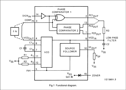
The intended purpose of the 4046 is to create a phase locked loop (PLL). The phase of an internal square wave oscillator is compared to the square wave from an external source. The phase comparator outputs a voltage that adjusts the internal oscillator until the two signals are synced.
My idea was to replace the internal oscillator in the 4046 with an external one.
The External PLL Oscillator
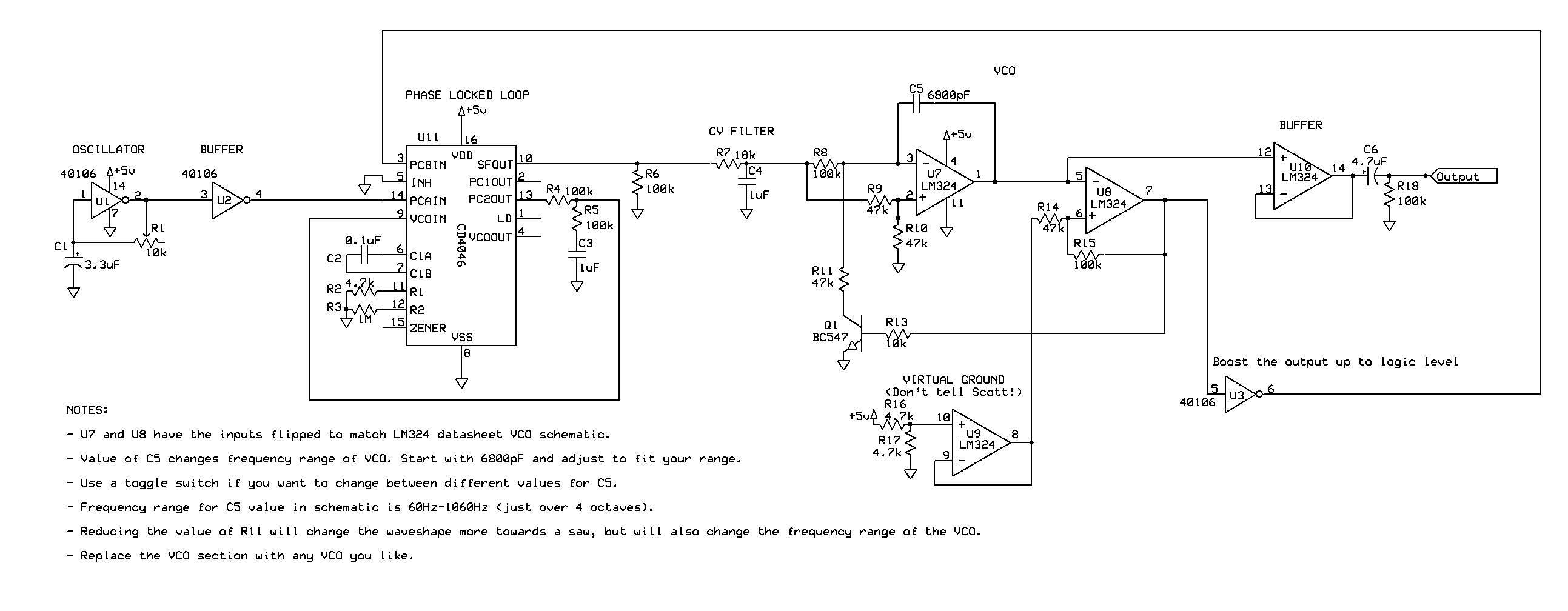
Any VCO would work, but for my experiment I had to find one that was simple and ran on a 5V supply. The LM324 opamp is a popular choice for Lunetta builders because it works well on a single rail power supply. I found an oscillator in the LM324 datasheet that creates both a triangle and square wave.
The plan was to convert a square wave to a saw, but even a triangle would do. A triangle can be converted into a saw, and this was just a test to prove that it could be done – the oscillator can be replaced with any other VCO. The only requirement is that there also needs to be a square wave output. Most oscillators do have a square wave output, but it is also very easy to create one using a comparator.
Putting It All Together
Once the oscillator was built and tested running independently, I sent the buffered source follower voltage out from the 4046 to the CV input of the external oscillator. Then I connected the square wave output from the external oscillator to the second phase comparator input on the 4046. The output from the LM324 was a little low, so I used a Schmitt trigger inverter to boost the square up to logic level. This also inverts the single, but that doesn’t effect the PLL at all.
I now had a triangle VCO that was being synced to a square wave source signal by using a PLL.
Huzzah!
Need to Test
- Arduino
- This would be perfect to pair up with an Arduino as the square wave signal source. The Arduino has a Tone function that easily creates a logic level square wave tone. Leaving the waveshaping to analog circuitry frees up the processor to do other things (like creating LFO and envelope control voltages with the PWM outputs).
- Dual Rail Power Supply
- This should work even better with a dual rail power supply. The increased power supply range should improve the frequency range. The 4046 has a max supply range of 15-18V depending on the manufacturer. This means that some adjustments and level shifting may be required if used on a dual rail supply. I think that running the 4046 from 0-12V will work. Then the square wave output of the external oscillator can be shifted and brought up to the 12V logic level. This might be as simple as sending the signal into a diode and then sending the output to a comparator or inverter.
- Expo Convertor
- The range was just over 4 octaves, which isn’t bad considering it was on a 5V power supply. An expo convertor might improve that range, but also adds more complexity. It probably isn’t worth it for most Lunetta projects, but I might try it anyway.
- Sawtooth VCO
- The whole point of this experiment was to convert a square wave to a saw. I will need to try a sawtooth VCO. I will probably do this when I test the dual rail power supply. Check back in the future for that update.


