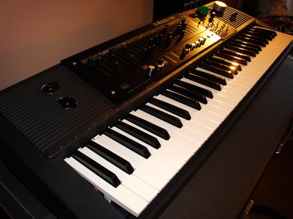
The C-MOnSter Synth is my first DIY synth project, and my first electronics project ever. It all start in the fall of 2010. I was looking up information on building your own fishing rods, and in the list of suggested videos was a series called How to Build a Synthesizer. I click on it and was surprised at how simple it seemed to start making noise. I bought the parts used in the video, and started testing out ways of expanding the simple 40106 Schmidt trigger oscillator that was shown in the video.
My first iteration had several oscillators tuned to a specific note and were toggled on using momentary switches.
I sent an email the person who made the video tutorial that got me started, Lorin Parker. I basically asked if my idea was a feasible. He gave some encouragement and suggested I look into using 4040 dividers to get even more notes. I took that idea and ran with it.
To build a top octave polyphonic synthesizer using almost exclusively simple CMOS based circuits, which will produce a raw gritty sound that will fill in a needed gap in my current collection of synthesizers.
An old Yamaha PSR I picked up for $25 provided the case and keys for the project.
A friend of mine does freelance audio work for a living and frequently checks various used shops to see what he can get a deal on. I asked him to keep an eye open for any old mixers or equalizer that I could use for the pots. He found an awesome equalizer with 24 sliding pots, 2 rotary pots, and 5 push toggle switches on the front panel. I decided to reuse the entire front panel and just mount it right into the Yamaha case.
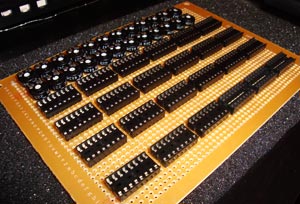
Twelve 40106 Schmidt triggers oscillators generate a 16′ top octave.
Twelve addition 40106 Schmidt trigger oscillators generate a 8′ top octave.
Both sets of oscillators can be toggled on or off using several 4066’s to do the switching.
The two sets of top octave notes are divided using 24 individual 4040 dividers. The outputs from these dividers each go to the appropriate key. Each key switches a note from the 16′ and 8′ divisions.
The sound is split and one division goes through a simple resistor/capacitor low-pass and then high-pass filter for wave shaping.
The other division from the oscillators goes to a Schmidt trigger. This duplicates the same waveform, but inverted when only one note is sent to it. When two or more notes are sent into it, the output is a merged version of the waveforms. This creates some interesting pulse width modulation and rhythms.
The output of the Schmidt trigger goes through a simple resistor/capacitor low-pass and then high-pass filter for wave shaping.
The output from the two divisions are then actively mixed. The inverted sound from the Schmidt trigger causes cancellation in the first division, creating some interesting wave shaping options.
Another 40106 Schmidt trigger oscillator provides the clock for switching a 4066. The rate of the clock is controlled by a pot. When open, the switch connects a pot with a capacitor to ground. This creates a low-pass filtering effect on the sound. The amount of filtering is controlled by the pot. The filtering can be strong enough to completely turn the sound off and on, or subtle enough to create a soft tremolo.
The sound goes into a 4040 divider. The top four divisions are mixed together to create a rhythmic sound. The output of the mixed 4040 outputs is passively mixed with the source sound using a pot. Using both 16′ and 8′ octaves with this circuit creates a rhythmic sound that reminds me of chiptune music.
The sound is sent into the Vdd pin on a 40106 that has an oscillator setup using the first two pins. The rate of the oscillator is controlled using a pot. The sound output is taken from the output of the oscillator. The oscillator modulates the power source, which in this case is the sound. The output of the oscillator is passively mixed with the source using a pot.
A 40106 Schmidt trigger oscillator provides the clock signal to a 4029. There is a toggle switch that allows the use of an external clock. A 4040 divider is used on the clock signal to provide easy tempo division (useful when clocking from an external source). The internal clock is also split and sent to an output so it can be used to clock an external device. The output of the 4029 is decoded using a 4514.
This provided up to 16 steps with a toggle to change the direction. I also added switches to shorten the steps to 4, 8 or 12.
The design of the oscillators doesn’t allow for voltage control, so the sequencer cannot control the pitch of the notes. Instead, the steps use toggle switches. The toggles control a 4066, which turns the sound source on or off. This allows a rhythm to be played by holding down the desired keys.
A pot with a capacitor to ground is used to control the length of the switching of the steps. This can vary from very fast clicks to sequential steps blending into one long step.
Due to the nature of the top octave design, it is very difficult to create a true envelope. Instead, a PT2399 digital delay IC is used to create reverb. It is used before the final filters in an attempt to create a fake release on the unfiltered waveform.
The Wasp is a famous analog synth from 1978. It is memorable because of its simple circuits and gritty sound (and the yellow color scheme). The filter uses a 4069 CMOS chip and two 3080 IC’s.
I replaced the 3080’s with a single LM13700.
The schematic I used has the option for low-pass, high-pass, band-pass and notch-pass. I also added a bypass option.
A pot was added to adjust the amount of distortion.
A decay circuit can be toggled on that uses a 4066 to create a voltage controlled decay. The 4066 is triggered by the sound source, which toggles on a pot with a resistor to ground on the CV input. The length of the decay is controlled by adjusting the pot.
I also added a pot to control the output level of the filter (used for mixing with the second Wasp filter).
An addition Wasp filter is used with a pot on the input that controls that amount of sound that comes from the first Wasp filter versus the sound from before both Wasp filters. This allows the two Wasp filters to be used in varying degrees of serial or parallel configuration.
A pot is used on the output to actively mix with the output of Wasp filter 1.
This was my first project, so there were many things that I learned along the way. I will share some of them here in the hope of helping other beginners.
- Start small. I dreamt too big with this project. I did finally complete it, but it took a year and most of my spare time.
- Modular is best. It allows you to work on small projects one at a time. Also, the signal path of your synth is not permanent. You can add new modules and change patches at any time.
- Start with a good stable power supply. Don’t count on virtual ground for complex circuits.
- Working on synths late at night (and after a few beers) can be dangerous. Be cautious!

