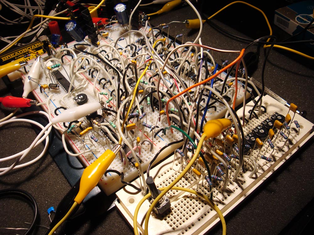
The idea for this experiment came while chatting with some other synth builders about digital FIR filters. One person had previously mentioned that a Lunetta delay circuit I had made was similar to a FIR filter. It used shift registers like a bucket brigade to delay pulses from a square wave Lunetta oscillator. The taps were divided by increasing amounts along the delay line. The idea was to emulate the decaying level of feedback (echo) in a bucket brigade delay circuit.
So I figured I would give it a try again, but this time with the intent of emulating a FIR filter.
Before getting into the details of this project, I have to make some disclaimers.
- This is an emulation of a FIR filter, and not a replacement.
- This circuit is entirely impractical. There are far easier analog methods to filter sound.
- This circuit only works with pulse waves. Other waveforms are converted into pulse before being used.
- This circuit is noisy due to the low sample rate.
With that out of the way, I can now get into the fun details.
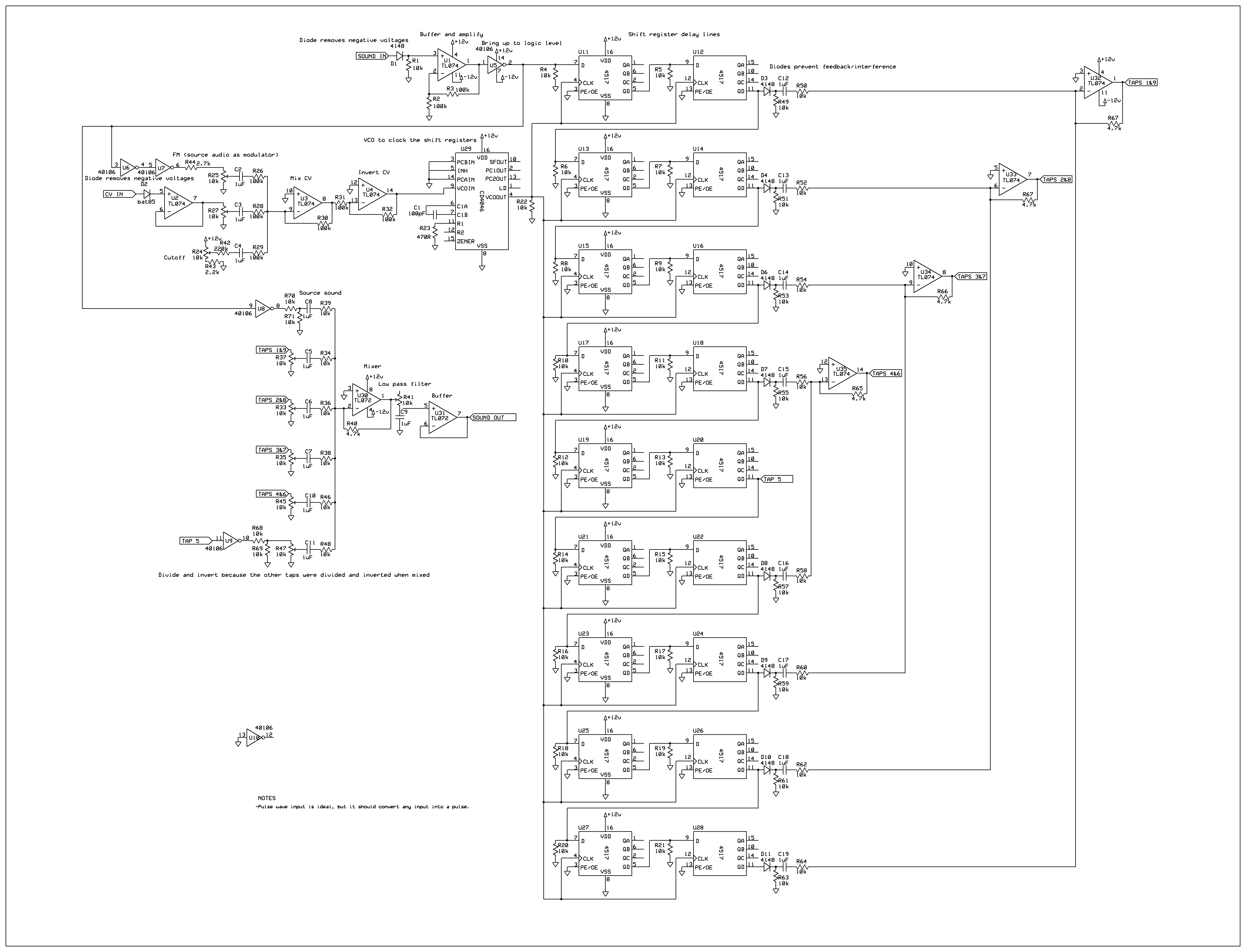
I powered the logic chips from +12V. This is because it is easy to buffer and covert the signals up instead of down, with less chance of doing damage from an input that is too hot. The eurorack standard for audio signals is -5V to +5V. The Vss on the logic chips was 0V, so I cut out the negative voltage using a diode. This left me with a signal that was 0V – +5V.
Since this is the same voltage range that you get from an Arduino using the Tone function, I bypassed the diode in my test and used the Arduino as my sound source. I already had code written to read MIDI, output a square wave and create a PWM envelope voltage. I had to do some conversion to change the voltage range of the envelope to max out near 12V, but I left that and the rest of the Arduino out of the schematic.
Since I wanted to control the sample rate of the delay line, I created a VCO. I used the square wave VCO from a 4046. I mixed the envelope from the Arduino (CV IN on the schematic) with the voltage from a pot wired in a voltage divider configuration. For extra fun, I also added a pot to mix in the sound input as a modulation source.
I used nine 4517 shift register chips for the delay line. These chips have two 64 stage shift registers. The registers in each chip were linked, and then each chip was linked. All the registers shared the same clock.
The initial test only used 3 tap points in the delay line. It was very easy to see what was happening to the waveform when I turned up the level on a tap. The tap was being added to the source wave, but after a slight delay. This delay made a step in the wave shape. As I increased the level on each tap, I could clearly see a new step start to emerge from the top of the waveform. Increasing the clock speed to the shift registers narrowed the spacing between each step.
Seeing this stepped waveform made me realize that I had already created a 1-bit FIR filter and had no idea that is what I had done. The circuit was similar to the delay circuit I had built, but all of the taps were full level. Also, the clock speed was synced to the source frequency so that the waveform always looked the same. An almost identical waveform could be created using the initial circuit that I created.
The initial test made some interesting sounds, but was a bit harsh and noisy. An RC low pass filter on the output helped, but didn’t fix the problem. There was a lot of buzzing and harsh harmonic sounds. To help, I increased the clock rate. I also started to investigate the option of increasing the number of taps.
While researching more on FIR filters, I discovered that many of them use symmetrical tap values. For example, in a five tap configuration, taps 1 and 5 are at the same level. Likewise for taps 2 and 4. I found a site that showed a data-flow configuration for how to achieve this symmetry. It was very easy to convert the data-flow to a schematic.
I made the symmetrical modifications to my circuit and used nine tap points. This greatly improved both the sound and controllability of the circuit. Check out the video below to see it in action.
A 1-bit approximation of a FIR filter can be realized in analog circuitry. However, its usefulness and practicality is debatable. It was a good experiment to learn about how a FIR filter shapes sound, but the circuit suffers from many problems. It is difficult and unintuitive to control all nine taps, it only works with pulse waves, and it is harsh and noisy. More taps and a higher sample rate will help, but I completely filled my breadboard with just the nine taps.

